
We will define the basic types of support
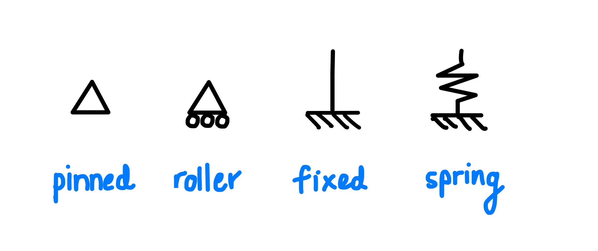
Of course, supports are not limited to the orientations shown below. Pinned/roller supports can be oriented horizontally too, provided that the correct structural detailing is done.
Pinned Support
A common pin support denotation is shown below.
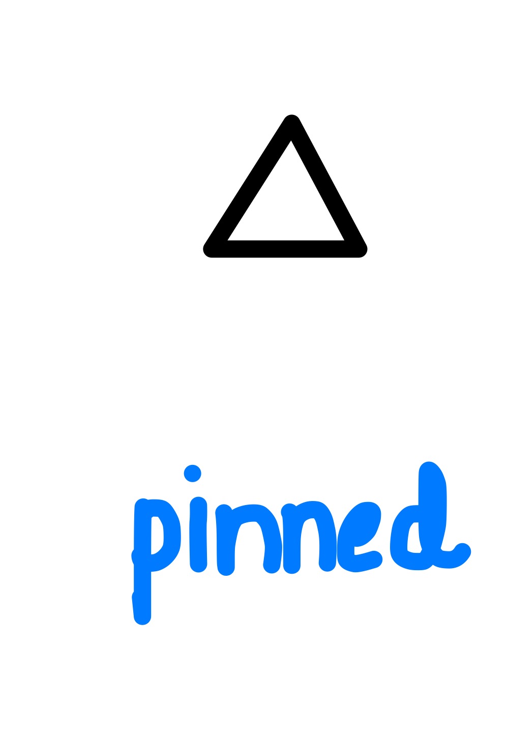
In general, bending moments are ZERO at pinned supports. However, if you have a continuous beam over a pinned support, then there may be a hogging moment at that support.
Roller Support
There are two main ways roller supports may be identified:
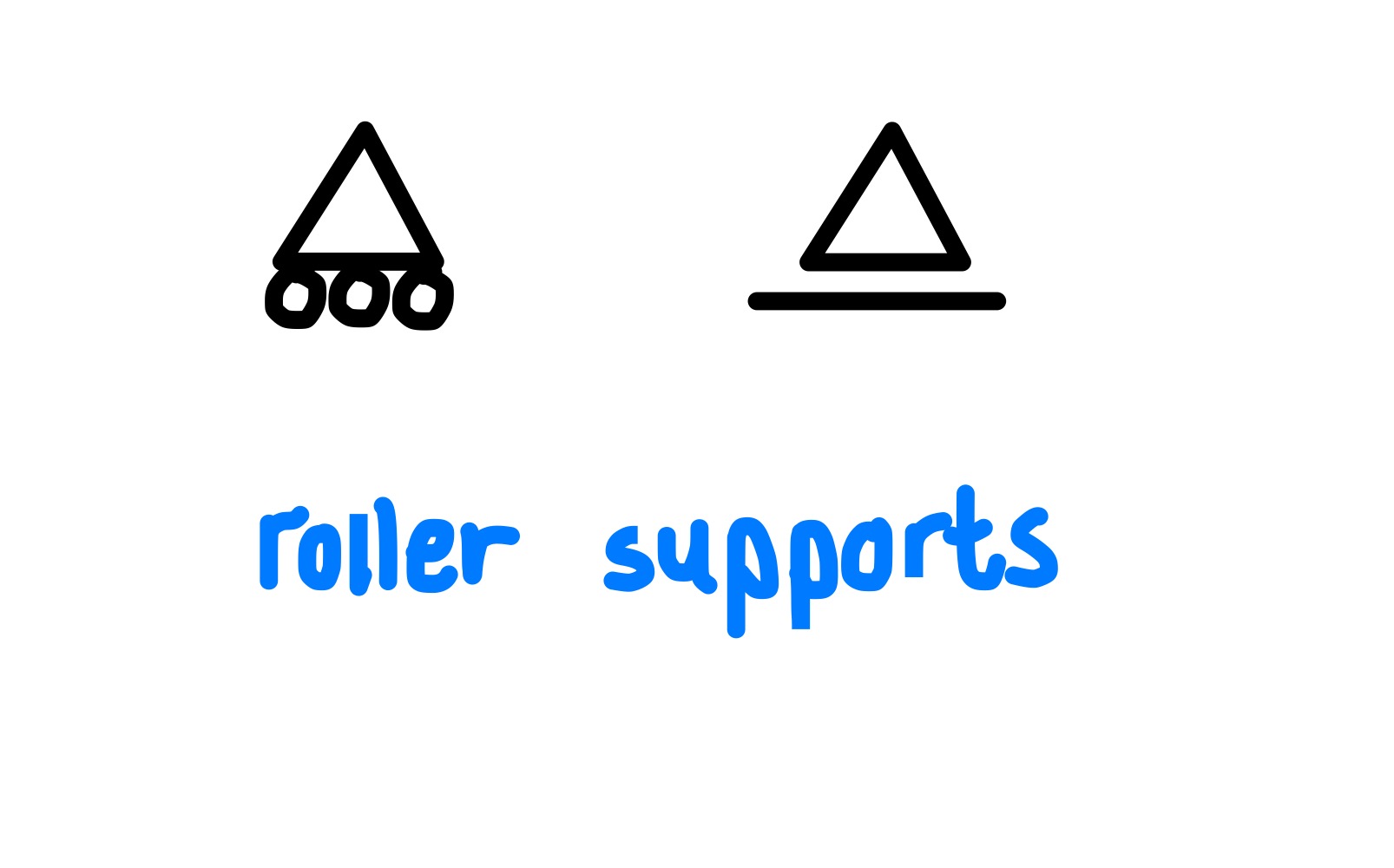
In general, the support on the left is commonly used internationally to denote a roller support. However, in Japan and some other countries, roller supports are commonly denoted using the support on the right.
Fixed Support
Fixed supports are identified as shown below:
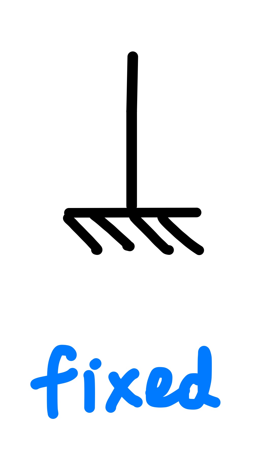
Fixed supports resist shear forces and bending moments.
Spring Support
We can also use spring supports to idealise supports which are not truly pinned or fixed. For example, the soil may have a certain amount of spring stiffness which we want to use in a finite element model.
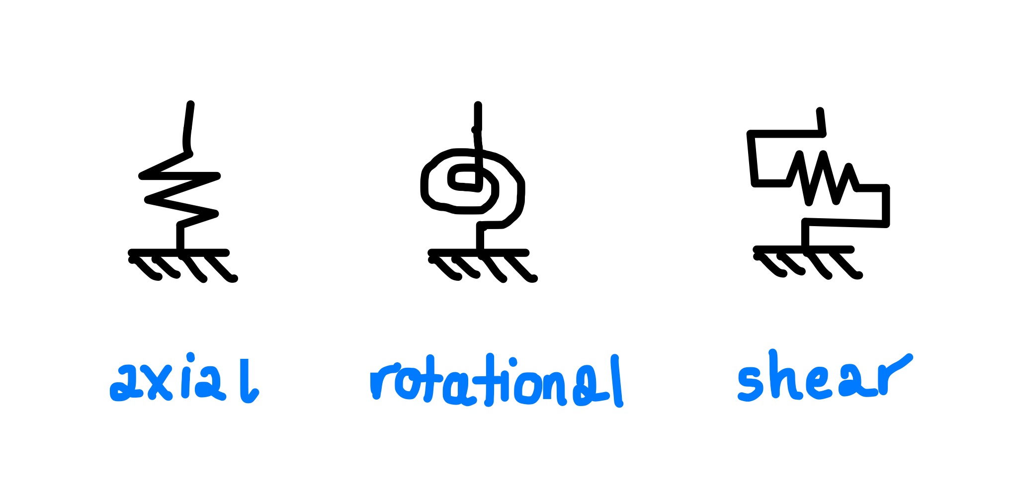
As shown above, there are various kinds of springs we can use depending on the situation we are trying to analyse. Springs can provide a very numerically cheap and accurate way to model the behavior of a structural system (for example, a seismic isolation layer).
Alternative Denotation System
In structural engineering software, sometimes support boundary conditions are represented numerically using degrees of freedom (where 0 means free, and 1 means restrained). This is very convenient for 3D analysis. Some examples are shown below:
| δX δY δZ θX θY θZ | Description |
| 1 1 1 0 0 0 | Pinned in all directions. Free to rotate. |
| 1 1 1 1 1 1 | Fixed in all directions and fixed against rotation |
| 0 0 1 0 0 0 | Roller support. Only supports gravity loads. |
| 1 1 0 0 0 0 | No gravity support. Only restrained laterally. |
Other
In addition to the above support conditions, members may have their own internal boundary conditions. The most important of these used in analysis software are
※ What are End Releases? Explained in 1-Minute
Furthermore, there are rarely any true pinned supports, and there are no true fixed supports. It all depends on the rotation capacity of the connections. It is up to the engineer to judge the most appropriate support condition for specific connections/frames. Some examples are provided below (coming soon).