Buckling is one of the key design risks to be addressed when designing structural members. If a member buckles, it could lead to significant stability issues for the structure. Furthermore, the member will be unable to develop its full plastic deformation. It is a member used for resisting lateral loads, it will not contribute to the lateral resistance of the structure after buckling.
How to Calculate the Euler Buckling Load?
The load at which bucking occurs is shown down below:
format('truetype')%3Bfont-weight%3Anormal%3Bfont-style%3Anormal%3B%7D%3C%2Fstyle%3E%3C%2Fdefs%3E%3Ctext%20fill%3D%22%23007F00%22%20font-family%3D%22Arial%22%20font-size%3D%2216%22%20text-anchor%3D%22middle%22%20x%3D%225.5%22%20y%3D%2229%22%3EP%3C%2Ftext%3E%3Ctext%20fill%3D%22%23007F00%22%20font-family%3D%22Arial%22%20font-size%3D%2212%22%20text-anchor%3D%22middle%22%20x%3D%2216.5%22%20y%3D%2234%22%3Ecr%3C%2Ftext%3E%3Ctext%20fill%3D%22%23007F00%22%20font-family%3D%22math1da1748c56a8e6b097a67ee67c2%22%20font-size%3D%2216%22%20text-anchor%3D%22middle%22%20x%3D%2229.5%22%20y%3D%2229%22%3E%3D%3C%2Ftext%3E%3Cline%20stroke%3D%22%23007F00%22%20stroke-linecap%3D%22square%22%20stroke-width%3D%221%22%20x1%3D%2240.5%22%20x2%3D%2277.5%22%20y1%3D%2223.5%22%20y2%3D%2223.5%22%2F%3E%3Ctext%20fill%3D%22%23007F00%22%20font-family%3D%22math1da1748c56a8e6b097a67ee67c2%22%20font-size%3D%2216%22%20text-anchor%3D%22middle%22%20x%3D%2248.5%22%20y%3D%2218%22%3E%26%23x3C0%3B%3C%2Ftext%3E%3Ctext%20fill%3D%22%23007F00%22%20font-family%3D%22Arial%22%20font-size%3D%2212%22%20text-anchor%3D%22middle%22%20x%3D%2257.5%22%20y%3D%2211%22%3E2%3C%2Ftext%3E%3Ctext%20fill%3D%22%23007F00%22%20font-family%3D%22Arial%22%20font-size%3D%2216%22%20text-anchor%3D%22middle%22%20x%3D%2268.5%22%20y%3D%2218%22%3EEI%3C%2Ftext%3E%3Ctext%20fill%3D%22%23007F00%22%20font-family%3D%22Arial%22%20font-size%3D%2216%22%20text-anchor%3D%22middle%22%20x%3D%2255.5%22%20y%3D%2243%22%3EL%3C%2Ftext%3E%3Ctext%20fill%3D%22%23007F00%22%20font-family%3D%22Arial%22%20font-size%3D%2212%22%20text-anchor%3D%22middle%22%20x%3D%2263.5%22%20y%3D%2250%22%3Ek%3C%2Ftext%3E%3Ctext%20fill%3D%22%23007F00%22%20font-family%3D%22Arial%22%20font-size%3D%2212%22%20text-anchor%3D%22middle%22%20x%3D%2263.5%22%20y%3D%2236%22%3E2%3C%2Ftext%3E%3C%2Fsvg%3E)
Where E is the Young's Modulus, I is the second moment of area, and Lk is the effective length considering the end support conditions.
One of the key observations to make is that:
format('truetype')%3Bfont-weight%3Anormal%3Bfont-style%3Anormal%3B%7D%3C%2Fstyle%3E%3C%2Fdefs%3E%3Ctext%20font-family%3D%22Arial%22%20font-size%3D%2216%22%20font-style%3D%22italic%22%20text-anchor%3D%22middle%22%20x%3D%225.5%22%20y%3D%2219%22%3EP%3C%2Ftext%3E%3Ctext%20font-family%3D%22Arial%22%20font-size%3D%2212%22%20font-style%3D%22italic%22%20text-anchor%3D%22middle%22%20x%3D%2215.5%22%20y%3D%2224%22%3Ec%3C%2Ftext%3E%3Ctext%20font-family%3D%22Arial%22%20font-size%3D%2212%22%20font-style%3D%22italic%22%20text-anchor%3D%22middle%22%20x%3D%2220.5%22%20y%3D%2224%22%3Er%3C%2Ftext%3E%3Ctext%20font-family%3D%22math1502cc2c94be1a7c4ca7ef25b8b%22%20font-size%3D%2216%22%20text-anchor%3D%22middle%22%20x%3D%2235.5%22%20y%3D%2219%22%3E%26%23x221D%3B%3C%2Ftext%3E%3Cline%20stroke%3D%22%23000000%22%20stroke-linecap%3D%22square%22%20stroke-width%3D%221%22%20x1%3D%2251.5%22%20x2%3D%2261.5%22%20y1%3D%2223.5%22%20y2%3D%222.5%22%2F%3E%3Ctext%20font-family%3D%22Arial%22%20font-size%3D%2216%22%20text-anchor%3D%22middle%22%20x%3D%2247.5%22%20y%3D%2217%22%3E1%3C%2Ftext%3E%3Ctext%20font-family%3D%22Arial%22%20font-size%3D%2216%22%20font-style%3D%22italic%22%20text-anchor%3D%22middle%22%20x%3D%2265.5%22%20y%3D%2223%22%3EL%3C%2Ftext%3E%3Ctext%20font-family%3D%22Arial%22%20font-size%3D%2212%22%20text-anchor%3D%22middle%22%20x%3D%2274.5%22%20y%3D%2216%22%3E2%3C%2Ftext%3E%3C%2Fsvg%3E)
In other words, a smaller effective length means that the onset load for bucking is much higher. Reducing the effective length gives us significant means to prevent bucking.
For
※ What are Secondary Beams? Role, Design and Connections. Difference with Primary Beams.
Calculation of the Effective Length
As mentioned above, the effective length is calculated based on the end support conditions of the structural member in question. The effective length is calculated as:
format('truetype')%3Bfont-weight%3Anormal%3Bfont-style%3Anormal%3B%7D%3C%2Fstyle%3E%3C%2Fdefs%3E%3Ctext%20fill%3D%22%23007F00%22%20font-family%3D%22Arial%22%20font-size%3D%2216%22%20text-anchor%3D%22middle%22%20x%3D%224.5%22%20y%3D%2216%22%3EL%3C%2Ftext%3E%3Ctext%20fill%3D%22%23007F00%22%20font-family%3D%22Arial%22%20font-size%3D%2212%22%20text-anchor%3D%22middle%22%20x%3D%2212.5%22%20y%3D%2221%22%3Ek%3C%2Ftext%3E%3Ctext%20fill%3D%22%23007F00%22%20font-family%3D%22math17f39f8317fbdb1988ef4c628eb%22%20font-size%3D%2216%22%20text-anchor%3D%22middle%22%20x%3D%2223.5%22%20y%3D%2216%22%3E%3D%3C%2Ftext%3E%3Ctext%20fill%3D%22%23007F00%22%20font-family%3D%22Arial%22%20font-size%3D%2216%22%20text-anchor%3D%22middle%22%20x%3D%2240.5%22%20y%3D%2216%22%3EkL%3C%2Ftext%3E%3C%2Fsvg%3E)
Where k is the end support factor and L is the unbraced length of the member.
End Support Factors
Some end support factors for buckling are illustrated below:
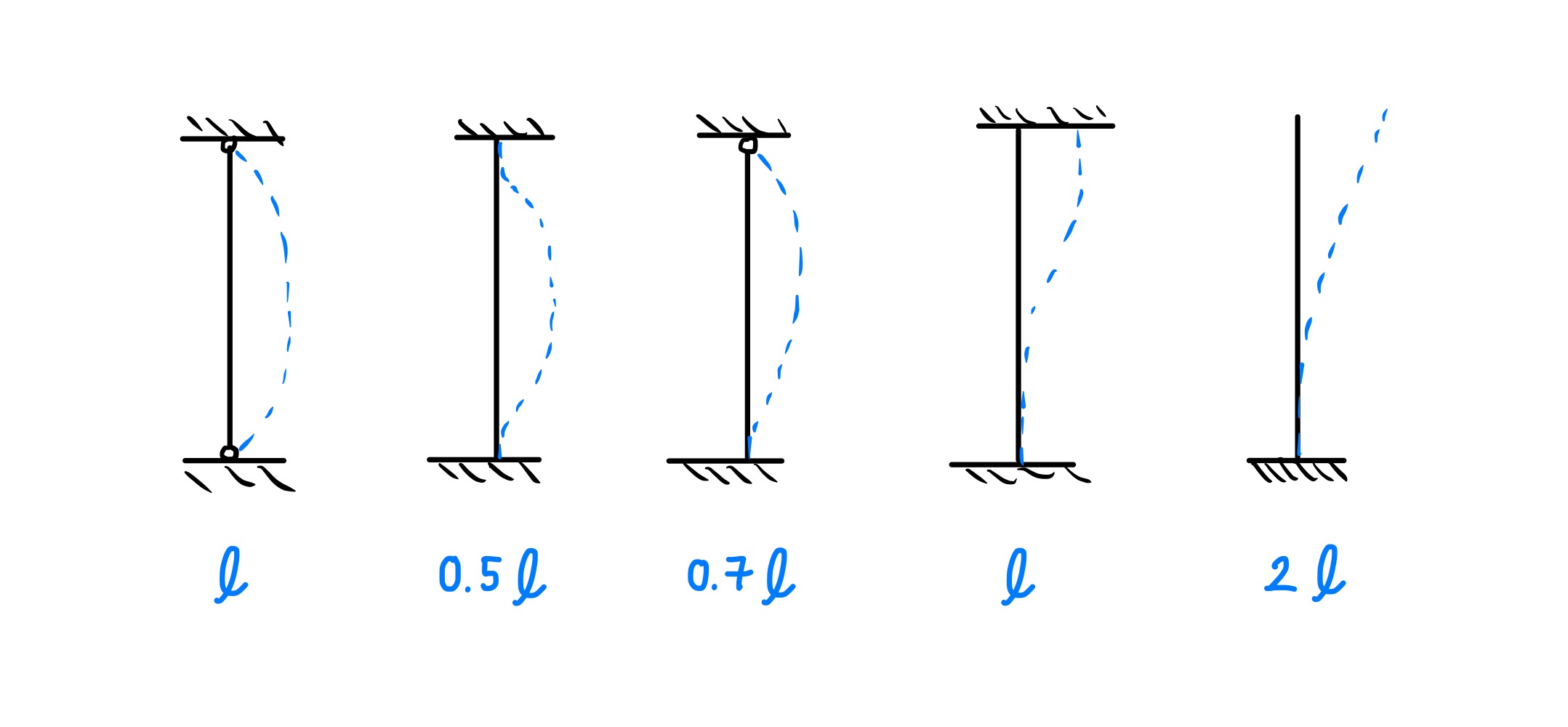
As shown above, the deflected shape for a member pinned at both ends is a half-sine curve, and this has a buckling factor of 1.0. For cantilevers, the deflected shape is half of a half-sine curve, and the buckling factor is 2.0. Finally, for a member fixed at both ends, the deflected shape can be considered to be two half-sine curves, and the buckling factor is 0.5.